Tobin
Metropolitan Ave
Test#2 2gal/min 3" 112deg water since 1", boiler thermostat calls HW, boiler starts 6" 112 deg, furnace reaches 140deg, HW heating/zone light on 9" 103.5deg, furnace 160 11" 107deg, furnace reaches 170 and turns off, HW still zone on/circulator running 14" 108deg, furnace restarts @ 140deg 16" 109 17" 110 18.5" 112, furnace off @170, zone on 19" water off 20" thermostat call-off, circulator on 21" 114deg after 1min 25" 114deg after 1min thermostat off, circulator off 28" 114 all off Water on 30.5" 114, boiler thermostat calls HW, boiler starts 31.5" 114 circulator on, furnace 140 33.5" 109 35" 106 36" 107
What is unsatisfactory about this? Is the water not hot enough?
Every time a hw faucet is turned on (@2g/m) the boiler kicks on in 0-3min. So the boiler is on whenever the how water dips below ~113. The boiler operation seems normal, running whenever there is a call for heat, cycling between its hilimit of 170 and low limit of 140 until the call for heat is satisfied.
When all is off and satisfied the boiler shouldn't go on as soon as you turn on the hot water. It defeats the purpose of the superstor tank. The boiler cannot and should not need to keep up with the demand.
The superstore aquastat has a hi limit and a differential. The differential is either factory set at something like 8F or is adjustable ~ 5-20F. Since you don't have a mixing valve you have to keep the temperature of the tank at 114 so nobody gets scalded. It doesn't take long to drop that temperature and then it is left to the boiler to continue its normal cycling yet never really catching up. The differential is not really a factor here.
proposal:
- add a mixing valve
- raise the superstor aquastat hi limit to 150
- set the mixing valve at 115-120
- start with a default superstor aquastat diff of 8F and tune from there
The hypothesis is that the boiler shouldn't come on right away. Less cold water should be required to refill the superstor since the 150 degree water is being mixed down to 115. It will take longer to drop to the differential setpoint delaying the call for heat to the boiler. the hot water temperature at the faucet should be more stable.
dong
The .. $10 billion-a-year behemoth ..eyes a North American expansion from its new office in Boston’s Financial District. “[DONG has] more experience than pretty much anybody in the world at this point,” said James Manwell, a professor at the University of Massachusetts Amherst and director of its wind energy center. Samuel Leupold, the head of DONG’s wind operations, salid the company recognized that the offshore wind industry was starting to develop in the United States..[and] acquire[d] development rights for 187,500 acres 15 miles south of Martha’s Vineyard. [In UK] its workforce grew from 10 in 2009 to 725 today, and hope that success can be replicated in the United States.
4505 N Haight Ave 97217 (NE)

porch details


electrical service
Section 250.53(G) requires that all rod and pipe electrodes have at least 8 ft of length in contact with the soil, regardless of rock bottom. Where rock bottom is encountered, the electrodes must be either driven at not more than a 45-degree angle or buried in a 21/2-ft-deep trench. Driving the rod at an angle is permitted only if it is not possible to drive the rod vertically to obtain at least 8 ft of earth contact. Burying the ground rod is permitted only if it is not possible to drive the rod vertically or at an angle. Exhibit 250.26 illustrates these requirements.
http://code.necplus.org/document.php?id=necss:70-2011:70_e250-26
A grounding electrode connector must connect the neutral conductor to a grounding electrode at a service drop, meter enclosure or service disconnect.
http://fyi.uwex.edu/mrec/files/2011/04/W4.-Biesterveld-NEC-grounding-MREC2010.pdf
phase1 finish
Tasks and stuff we need on site by 7/30.
In order to liven up the new circuits we have to eliminate most of the old including electric heat, drier, electric stove, dishwasher. Is your hot water heater gas?
So we need the new stuff there (and be ready to reinstall dishwasher??).
What you are going to do about kitchen cabinets is a big question.??
tools
those doing finish carpentry each nead
- nice block plane
- chisels
- utility knife
- tape measure
- square
- 16oz finish hammer
- nail set
- cats paw
- coping saw
- wire cutters
to bring??
- bisquit jointer
- HVLP sprayer
- router
to bring
- grinder sharpener
- finsh nailer
- battery drill
- battery jigsaw
- brad pusher
- caliper
- block plane
- chisels
- utility knife
- tape measure
- square
- 16oz finish hammer
- nail set
- cats paw
- coping saw
- wire cutters
electrical
- linesman's pliers
- romex stripper
Tasks
- hook up gas line
Stuff
- gas stove
- sell electric drier, buy gas drier
- all light fixtures, bulbs and fan
- finish/guts for the shower/tub valves
- toilet
- sinks and faucets
- cabinets??
- convectors/radiators(can't really do finish carpentry til they are in
- finish carpentry stock
http://www.treeproductshardwood.com/666845.html
http://cascadehardwood.com/products

phase2 framing
bath structural repair
 Lap joint would be nice but is unnecessary. Maybe with your little skill saw. You can use fiberglass insulation for sill sealer in a pinch. PT sill but the rest doesn't have to be. If you have to scab on make them about 3'
http://www.awc.org/helpoutreach/ecourses/DES110/DES110eCourseV02-2011.pdf
post locations
current plan is on google drive as Haight/cadfiles/haightTimA3.dwg
The distance between the corner 2x6's of the addition and the new 6x8 posts is 6'4-1/4" (inside to inside). The posts sit 4" in from the south and north outside frame of the addition. Suggested procedure would be to check for clearance (mainly from pipes). If a joist passes through that is probably OK. We can cut it out of the way and hang it from the post.
Let me know what you find.
Assuming everything is OK
- cut a 6 1/2 x 8 1/2 hole in the floor at each location.
- make that the center of the 30x30x12? (look at plans) footing dug to bearing soil.
- Cross up some rebar and bent bars pointing up.
- Set up a 10x10x whatever is convenient box over the footing.
- pour the footings and posts from up above.
- sink an anchor bolt in the center of each.
porch footings
- dig a narrow hole to bearing soil > 14"? deep at each corner of the porch. Bell out and flatten the bottom.
- suspend and support a 10x10 box over each.
- establish an elevation for each that is 9+ inches below from whatever you want as porch floor level.
- throw in a few rebar in each
- pour to your elevation line
- throw an anchor bolt in each
description
http://www.youtube.com/watch?v=lLsTdjzpikU&feature=youtu.be script
- all the forgotten cad
beam calcs

We can assume uniform loading with the beam supporting the weight of half of the front roof that connects to it, the other half being supported by the front wall. The rafters that bear on the beam span 13'9 1/2" from the beam to the inside of the front wall of the house and are at a 7/12 pitch which makes them 16'6" long. The top edge of the beam (where these rafters land) is a little less than 16' long. Snow load in Portland Oregon is figured at 20lb/sf and the dead load at 10lb/sf.
Typically the calculation is based on the (run * width * load(in lbs/sf))/2 since the front wall takes half the weight and it would be <math> \frac{14ft * 16ft * (20+10)\frac{lbs}{ft^2}}{2}=3360lbs</math> is the weight the beam must support.
In this case the beam not only has to resist the downward component of the weight but also the lateral component.  Separating them you get:
<math> \frac{16.5ft * 16ft * (20+10)\frac{lbs}{ft^2}}{2}=3960lbs</math>
<math> lateral = sin(arctan(7/12))*3960= 1995lbs</math> and
<math> down = cos(arctan(7/12))*3960=3402lbs </math>
beam data
F_b (fiber stress) in lbs/in^2 for
- /#1 Douglas Fir Larch = 1350lbs/in^2
- /#1 Hem Fir = 1050 lbs/in^2
F_v (horizantal shear) in lbs/in^2 for
- /#1 Douglas Fir Larch = 85lbs/in^2
- /#1 Hem Fir = 70 lbs/in^2
E (modulus of elasticity) F_b in lbs/in^2 for
- /#1 Douglas Fir Larch = 1,600,000
- /#1 Hem Fir = 1,300,000
for a 6x10 dressed beam the Section Modulus (S) is:
- S_xx = 82.73 in^3
- S_yy = 47.89 in^3
for a 6x10 dressed beam the Moment of Inertia (I) is:
- I_xx = 392.96 in^4
- I_yy = 131.71 in^3
Maximum bending moment (M)
of a beam is a product of its fiber stress F_b and section modulus value S.
So
<math>M = F_b*S</math> and
<math>M_{xx} = 1050\frac{lbs}{in^2}*82.74in^3= 86866lb-in</math> and
<math>M_{yy} = 1050\frac{lbs}{in^2}*47.89in^3= 50284lb-in</math>
For Uniformly loaded beams
<math>M=\frac{3*w*L^2}{2}</math> or
<math>w = \frac{2*F_b*S}{3*L^2} \frac{lbs}{ft}</math>
So:
<math>w_x = \frac{2*1050*82.73}{3*16.5^2}=213\frac{lbs}{ft} * 16.5ft = 3509lbs</math>
<math>w_y = \frac{2*1050*47.89}{3*16.5^2}=123\frac{lbs}{ft} * 16.5ft = 2031lbs</math>
So a 6x10 beam in eather #1 Doug fir or #1 Hem Fir will work in bending.
Deflection (fully loaded with snow)
<math>\Delta max = \frac{w kips/in* l in^2}{8}</math>
<math>\Delta max_x = \frac{\frac{213/12}{1000})*(16.5*12)^2}{8} =.60 in = 5/8in</math>
<math>\Delta max_y = \frac{\frac{123/12}{1000})*(16.5*12)^2}{8} =.35 in = 3/8 in</math>
Horizontal shear
V= weigh on each end of beam, b= width, d = depth
F_v must be less than the hem fir value of 70
<math> f_v = \frac{3*V}{2*b*b*d} <70</math>
<math> f_v = \frac{3*3509/2}{2*5.5*9.25} =51<70</math>
heat and hot water
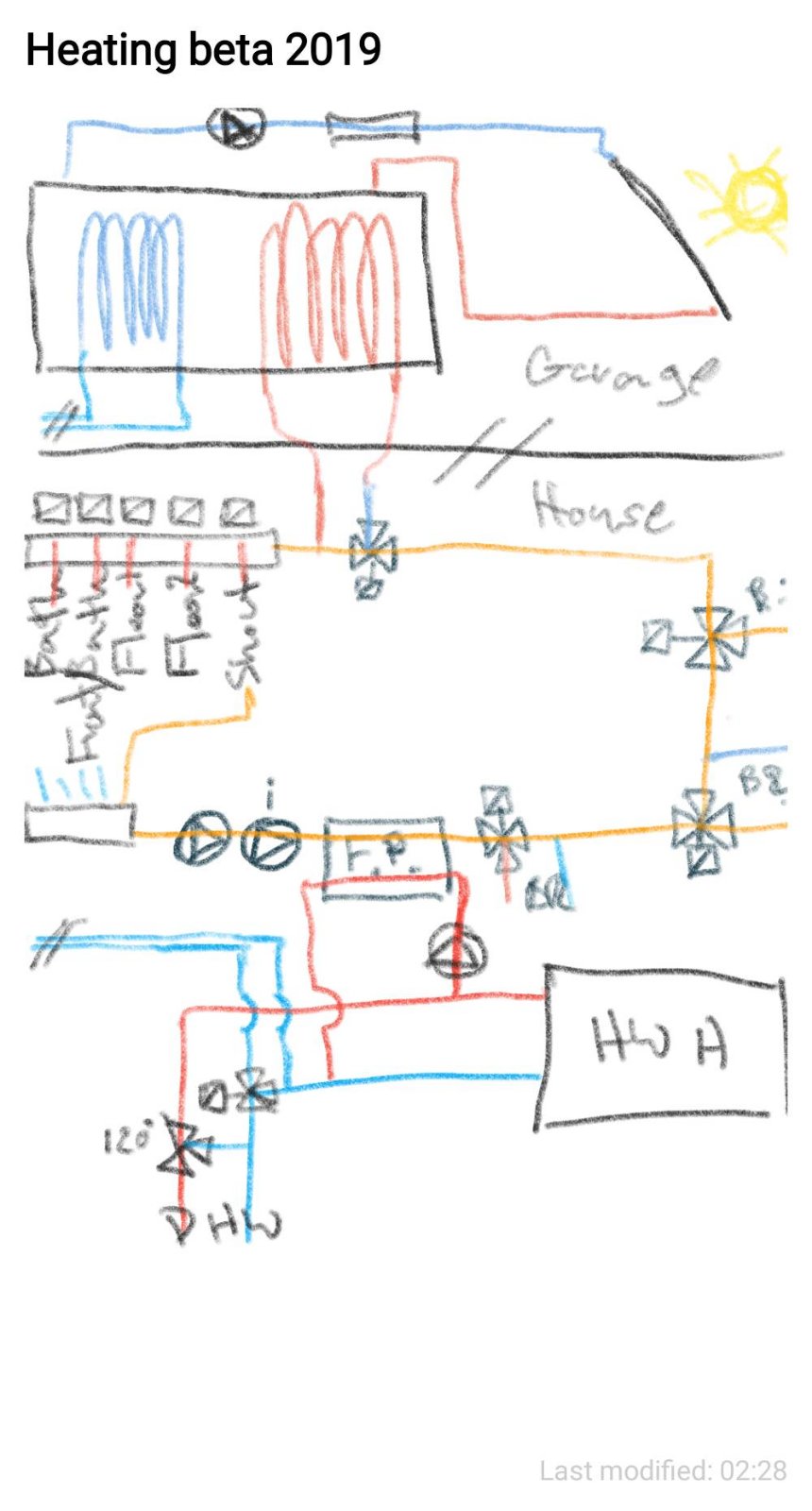
heating-beta-2019
https://www.builditsolar.com/Projects/SpaceHeating/Manual_of_Modern_Hydronics_Appendix.pdf
narrative(for darwing)
questions
narrative
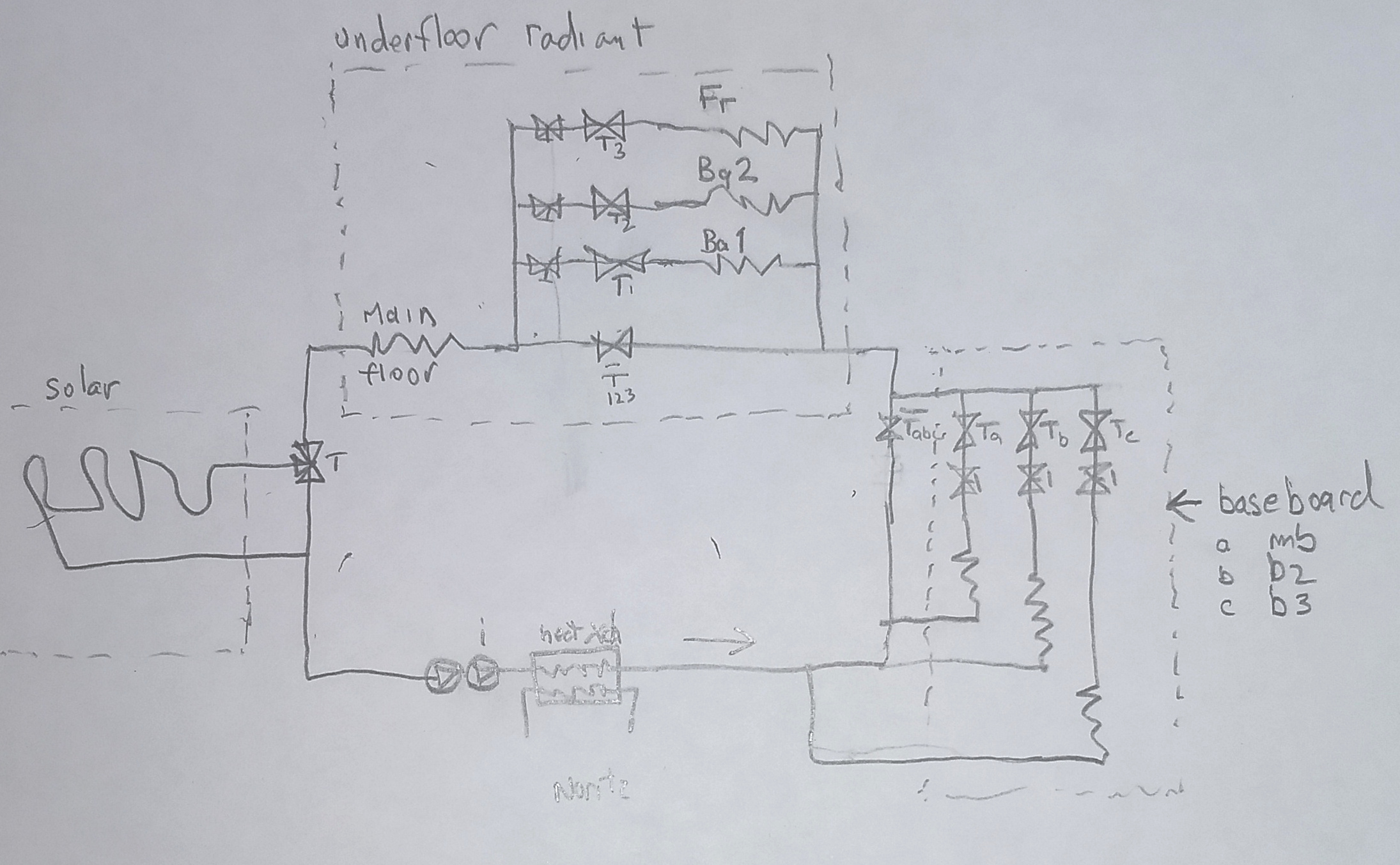
- The idea here is that for both the radiant and the baseboard sections operate similarly and independently. Whenever anywhere else calls for heat that(those) zonevalve(s) open(s) and the bypass zonevalve closes. Threeway valves don't seem to be a good idea in cases where there are more than one alternative path.
- Balancing for radiant and baseboard sections would be accomplished statically using ball valves. For these sections balancing only matters when more than one alternative paths are activated at the same time. Lets say the front door section(fr) and first floor bath(ba1) are both calling for heat. Balancing to favor ba1 would leave ba1's ball valve open and fr's zone valve would be closed a bit to send more heat to ba1. Then you would redo the exercise with all three (fr, ba1 and ba2) calling for heat.
questions
- important to have 2 way zones instead of 3 (tob)
- Still has to be balanced (tob)
- re narrative: Is that the balancing you mean?

- The idea is based on not having to have a manifold balanced or additional back pressure from balancing zone valves when only one zone is open, at lest for the baseboard rooms. This drawing includes azone for the living room which I think should be included so as to not need modifications in the future. I think I will keep the lines going to/form the FP-exchanger in Pex so that it is more flexible or that can be an upgrade once I have more soldering experience. I am going add drain valves for flushing the heater as well.
Considerations
- Thinking of using shark-bite fittings (https://www.homedepot.com/p/SharkBite-3-4-in-Push-to-Connect-x-FIP-Brass-Adapter-Fitting-U088LFA/202270501) to make the connections to pex so that I can take it apart easier if i need to.
- Still trying to understand what is necessary on this system with regard to expansion tank/backflowpreventer/dirttrap/airseparator
- I'm going to work on a shopping list based on this drawing. Send feedback.

- I realized that the mixing valve wont work unless there is a pump on the other side of it. May have to control for temperature another way.
- I may have to rearrange the valve layout if the normally closed outlet is not always on the same side.
- I moved the solar input to be in front of the first loads.
- All valves are included except the elbows and reducing Tees/Sharkbite pieces. If I order tomorrow I can get almost everything on the day after Christmas.
temporary heat

quick and dirty
- From the hot water leaving the heater add a tee into the heat exchanger. Connect the brass pump to the other side of the heat exchanger and tee that into the cold water line going into the heater.
- Opposite the cool water leaving from the exchange is the hot water going to the heating elements. Connect to master bedroom baseboard in series with other bedroom baseboard in series with the manifold. Connect the three floor loops to each side of the manifold. Connect the other end of the maniflod to pump and then back to the heat exchanger.
- Connect both pumps to a relay. Everybody makes a $50 relay like this Taco Connect a thermostat to the relay. YOU ARE DONE.
You need:
- thermostat
- relay
monitor
- Start with the Noritz at 140F. Check temp going into the maniflold. Turn the Noritz down until it is warm but not hot to the touch. Keep checking. Turn off the heat when you take a shower. Don't burn yourself, it's 140F.
temporarily fancy
As fancy as it gets would ...
- put the thermostat in series with a NC flow switch that opens when somebody turns on the hot water.
- put the thermostat and the flow switch in series with an Hi Limit Aquastat mounted on a piece of copper pipe right before the manifold. Set it to shut to open if the water is >120F going into the radiant.
controls basic
- a $50 basic Taco relay will switch both pumps
controls fancy pricey
- SPDT Flow switch SPDT is like a 3way, gives you normally open and normally closed I think. Connect after tee coming from water heater.
- Honeywell High Limit Strap-On Aquastat, 65°F to 200°F L6006C1018
controls cool and cheap
in series with a NC flow switch and a NC High Limit

Noritz Professional Plumbing Diiagrams

BOM
Tank **Purchased**
Panels x2 **Purchased**
Heat circulators (2x)
- Wilo ECO 16RFC Variable Speed Cast Iron
- other
Solar prime
- Wilo 4090767
- other
Secondary Heat Loop (DHW)
- Wilo Strar 3 BS7. 1-speed bronze, 1/20HP, (3/4")
- other
Solar Circulator
- Calefi 256 Drainback Solar Pump Station
- price with Grundfos UP15-100
- price with NA26711 DC-EMC solar pump
- Calefi NA26711 DC-EMC solar pump (Stand alone)
- El Sid 10PV
Stand alone Normally open Zone valve
- Caleffi Z1 zone valve (normally open)
- Honeywell V8043B1027 (or a 3/4 120v AC normally open with terminal connections)
3 port Distribution manifolds (x3)
- Caleffi 668 Twist-flow manifold (#6686C5S1A)
- Any other manufacturer with flow meters and valves
Zone valves for all zones
- correct valves for manifold selected
Flat Plate Heat Exchanger
Sizing
@ Pex Supply
- http://www.pexsupply.com/Hydronic-Heat-Exchangers-FP-Series-5-822000
- 30-plate-1-1-4-Thread-60-GPM-Heat-Exchanger-5-x-12 - $638
@Outdoor Furnace Supply
- flatplate-brazed-30-plate-gbe-5x12 - $269 exact same model as the $638 one from Pex Supply
- Brent Industries LLC-brazed-40-plate-gbe-5x12 $226 not GEA-Flatplate brand
as bad as this design can handle w/ 30 plate worst-case calcs
pumpsIndirect Hot Water TanksLamana Thermal Austria Email SISS tank **Purchased** Vissmenn Vitocell-B 100 link tech specs Triangle Tube "Smart Multi-Energy 70" See google docs for specs pdf Austria Email SISS tank Other Optionshttp://www.craftsmanpipelining.com/ calcsKind of quick and dirty. Even though the relationships are really diffeqs with <math>\frac{dT}{dt}-k(T-T_0)</math> I kinda fudged it using averages. turns out the temperature of the DHW on the way to the shower only drops 3 ° so assuming it is constant isn't terrible. Assume you have an instant tankless hot water heater that, on its way to the showerhead, drops some heat into the tank used for radiant space heating, by passing through a heat exchange coil in the bottom (cool portion of a statified) tank. Maybe they are gonna want 140 ° DHW water because of Legionaires. How many BTUs are transferred in 1 hour between water at 137 ° and 110 ° if there is 8sf of copper heat exchange tubing?
h = 60\frac{BTU}{ft^2 hr ^{\circ}F}, \Delta T=27 ^{\circ} F </math>
Q = h\Delta T A </math>
Q = 60\frac{BTU}{ft^2 hr ^{\circ}F} * 27 ^{\circ}F * 8ft^2 * 1hr = 12,960Btu </math>
How many linear feet of 3/4" copper tubing is 8sf
ft = \frac{8ft^2}{\frac{3}{4}\frac{1}{12}\pi} = 40.7ft </math> At 5gpm what is the flow rate in 3/4 copper tubing?
How long does it take water to move through the heat exchanger at 5gpm?
How many BTUs get transferred in 11.3 seconds?
If 40.7BTUs get transferred out of the hot water how much does its temperature go down?
How much does the temperature go up in a 100 gallon tank if you took a shower for 1 hr?
How much does the temperature go up in a 100 gallon tank if you took a shower for 10 minutes?
OK, so assuming there are other sources dumping some heat into the tank what would it look like to use the top heat exchange coil as a pre-heat for the tankless hot water heater? How much would it raise the temperature of the incoming water (@5gpm 50 °)? How much heat would the tank lose?
How much heat would be transferred in an hour?
h = 60\frac{BTU}{ft^2 hr ^{\circ}F}, \Delta T=67 ^{\circ} F </math>
Q = h\Delta T A </math>
Q = 60\frac{BTU}{ft^2 hr ^{\circ}F} * 67 ^{\circ}F * 8ft^2 * 1hr = 32,160Btu </math> How much heat would be transferred in the 11.3 seconds it takes the water to go through?
If 101BTUs get transferred into the cold incoming water, how much does its tempertature go up??
So with the pre-heater happenning you are losing 32,160 Btus an hour while you get 12,960 back as the hot water passes through so you end up with a net loss of 19,200Btu/hr while the shower or whatever is on. If you know the continous flow at a a certain ΔT degree rise and the size of the tank can you figure how many btu's have been transferred to that water.?
Using techtanium specs and Assuming the ΔT rise produces water at 120 degrees, and knowing the heat exchanger water is kept at 180 °F then:
Q = h\Delta T A, h=\frac{Q}{\Delta T A} </math>
h = \frac{220,000BTU}{26ft^2 *\frac{120+50}{2}60^{\circ}F} =89 </math> This is a hard problemEven Siegenthaler comments in one of his articles how it is impossible to design a system given the specifications from the tank mfgrs. I no longer worry about getting ahead of you or behind you on this. I wonder if even our combined time and efforts will be enough soon enough. So what if 377gph steady state at Δ T of 70 degrees means you need 220,000btu/h. If you try to plug that back into Q= h*A*ΔT and you know it expects 180° from the boiler then 180-what? = ΔT ??? Is 'what' the average tank temperature? (outlet-inlet)/2 (120+50)/2 ?? BTW what is your cold water temperature in the winter? I recall it seemed cold even in summer? For the full out steady state <math> h = \frac{Q}{\Delta T A} =\frac{220,000BTU}{26ft^2 *(180 - \frac{120+50}{2}{\circ}F)} =89 </math> which seems to be higher than that 60-80 range. But a Δ T of 90° is possible from the spec it just means lower average flow rate to the shower still sucking down 220,000btu. You can jerry rig the h calculation to be the same by adding 10 degrees to the output temp and subtracting 10 from the input: <math> h = \frac{220,000BTU}{26ft^2 *(180 - \frac{130+40}{2}{\circ}F)} =89 </math>I don't trust 89 for h any more than I trusted 60. So then I'm back to research and I find the stuff below: OK so the spec represents a flow rate of 14gpm and a boiler side temp of 180 °. In an hour, does the mass of water that goes through the heat exchanger actually produce 220,000btu's? What's the &Detla;T of the heat exchanger?<math> Q = m*c*\Delta T, \Delta T=\frac{Q}{m*c} = \frac{220,000btu}{14\frac{gal}{min}*\frac{60min}{hr}*\frac{8.35lb}{gal}*.999\frac{btu}{lb*hr*^{\circ}F}}==31^{\circ}F</math>Now you gotta shift that and make 180 the average heat exchange temp which makes the input to the heat exchanger ~195 ° ie (165+195)/2 = 180 and ΔT=31 research
another interesting tidbit from Dwivedi:
designsummary of current design
space heating designA low temperature 'junk heat' system designed to meet the design temperature load of 25,000 Btu/hr. Most of the space heating is provided by radiant floor heating, most of that through a high thermal mass radiant slab with water at ~100 °. The remainder is provided by panel radiators designed to operate at 120 °. The radiant floor water is drawn from the middle of the 119 gallon storage tank. The panel radiators draw their water from the top of the tank. A evacuated tube solar panel takes water from the bottom of the tank and returns it to the upper region of the tank. The water in the tanks is at atmospheric pressure. The tank is used for heat storage and as the drainback tank for the solar collector. The level can be determined through the sight glass and is maintained by the user. The intent is to maintain stratification of temperature within the tank Additional heat for the storage stank is provided through heat exchange from the DHW system. domestic hot water designInstant condensing hot water heaters from Navien, Takagi and Noritz all can be configured for use with indirect hot water heaters and allow for solar pre-heating of cold water input. Cold water enters the the water heater via the storage tank using the upper heat exchanger coil to preheat the water. Hot water at 140 ° leaves the heater and again enters the storage tank, this time through the lower coil. After leaving off some heat back in the tank the water continues on to showers and other residential devices. This 'priority' circuit provides DHW. The water that loops through the lower coil can, under certain circumstances, recirculate back into the heater inlet. In short, during the heating season, when the water in the tank falls below a certain temperature this circulator is activated. discussionpriority by designThe advantage of preheating the DHW heater input is that for these on-demand heater units deliverable flowrate correlates inversely the inlet and outlet temperature difference so reducing that difference increases your flowrate. During DHW demand, more heat is taken out of the tank in pre-heating the water than is returned on its pass through the lower coil. The temperature difference is greater between The cold supply and the hot water in the top of the tank than it is between the heated DHW and the water in the lower section of the tank. When the tank 'calls' for heat and there is little or no DHW demand, the heat delivered to the lower coil is no longer offset by that lost by the upper coil since no (or little) water is flowing through the upper coil. During DHW demand the space heating system pitches in by preheating the water, in effect giving 'priority by design'. flipping the paradigmMost designs using indirect heating tanks have the DHW in the tank heated indirectly by the boiler loop (and possibly solar loop) running through the helical heat exchange coils. In this design the tank water is not used for DHW but is merely a junk heat repository of relatively low temperature water sent out to the domestic space heating emitters and for low temp solar or other inputs. The potable DHW runs through the helical coil heat exchangers on its way to satisfy DHW requirements of the household. The system takes advantage of the efficiency inherent in a condensing hot water heater operating at low temperatures. Even when providing for space heating requirements it cool temperature water from the bottom of the tank that is transmitted to the heater. stratifying for emitter typeThe high mass radiant slab heat gets warmed up at the beginning of the heating season and stays warm at around 100 ° until the outdoor sensor tells it that summer has arrived. This thermal mass is located in the center of an open-plan living area. The flow rate need not be great nor does it require adjustment (other then a mixing valve bypass to prevent overheating). The other emitters can respond quickly to the ambient temperature in each room via their thermostatic radiator valves. The low mass system adjusts to demand automatically via the pressure regulated variable speed regulator. These emitters are located for the most part in bedrooms and rooms not part of the central open-space core of the house. The need for hydraulic separation is greatly reduced since the 'boiler' is isolated in its own loop running at a modest flow rate. The tank acts as a buffer between the source and the emitter loops and as a buffer between the flow requirements of the high mass and low mass emitter loops. reducing the costs of solarDrainback tanks can cost as much as $600 and add complexity to the solar subsystem. Here the pump will probably need to be variable speed, able to overcome the head requirements for refilling the system and then throttle down adjusting its flow to solar conditions. (Or maybe there can be second pump in series that only comes on for filling). In any event it would be a good idea to limit drainback to only occur to respond to freeze or tank overheating danger. Perhaps that can be accomplished by placing an electrically operated valve that allows air into the solar loop at its zenith (high point) during those conditions that require drainback. (Maybe allowing air in anywhere, not just the top, would cause it to drain) Solar collectors work better with a high ΔT so maintaining the statification in the storage tank is important. Drawing water from and returning it at a tank levels with similar temperature reduces tank mixing and increases stratification. Low flow rates (particularly for entering water) lessen mixing as well. control freakSome controls would be nice to have but don't need to be implemented right away. Control you need now:
potential design problemsBad engineering is...being more concerned about how something looks than proving your design concept. Maybe its more a carpenters view of the world. If you are going to reverse the typical paradigm of dhw in the tank and heating in the heat exchanger then test that first. Hook it up, see what happens. Warm your house, take data by putting your hand around the pipe, and a thermometer in the room, cobble together something, be creative. Don't get lost in the details or become a super consumer of fancy crap that costs a fortune. If you are going to buy something know the price you are looking for and your buy point before you even ask for a quote. Never buy shit without first pricing cheaper alternatives and comparing. Be warm, show some economic sense, set priorities, get shit done. And if you borrow tools don't bring them back and throw them in the back hall. open vs closed systemSome people talk about open systems as systems in which the potable water goes through the heating loops. This is not the issue in this design nor is it the definition that applies. The definition that applies is...
Open systems are systems that run at atmospheric pressure. In the proposed design the storage tank is used as a drainback tank for the collectors and is kept at atmospheric pressure. The potential problems are.
http://www.crtech.com/flocad.html http://www.tfd.chalmers.se/~hani/kurser/OS_CFD/ http://www.fluidflowinfo.com/products.php Soler Thermal Combi System Designs http://www.caleffi.us/en_US/caleffi/Details/Magazines/pdf/idronics_6_us.pdf Other system ideas http://www.trendsetterindustries.com/sites/default/files/Multizone.pdf Hydronic Piping Codes http://ecodes.biz/ecodes_support/free_resources/Oregon/10_Mechanical/10_PDF/Chapter%2012_Hydronic%20Piping.pdf
other design stuffSample problem: given the above specs, if you used one coil connected from tankless system delivering at 6gpm and 140 degrees-
You know:
240gph = 4gpm on calculating head loss
3way diverter valves
Hi, I am impressed with your Ergomax indirect tank product and your approach to system design. I am involved with groups who are working on HVAC/DHW alternatives in the Northwest based upon 'junk heat'. This is related to radiant hydronic designs with pex embedded on the slab requiring only 100 degrees F. Your approach of running the DHW through the heat exchange coil is intriguing. We are looking to implement systems in which the DHW comes from an on-demand instant HW heater (like those from Navien or Rinnai), and, on its way to the shower head, goes through a heat exchange coil, delivering some heat to a tank. The water in that tank is then circulated into the low temp hydronic system. Additionally, other sources like heat from our woeful 2-5 sun-hours a day solar collectors could be added to the tank water. Our basic questions are as follows:
Thanks, Tim McKenna 857 498-2574
John SiegenthalerWhat kind of mechanical system fits the needs of these builders? Here’s a listing of the qualities I feel should be part of the solution. 1. A highly efficient, modestly sized, modulation/condensing, sealed combustion heat source. It could be a “box” that goes on the wall, or an assembly that fits onto or into a storage vessel. For reasons that will become apparent as you read on, a burner turndown ratio of 3:1 is very sufficient. There is no need to complicate the solution with the controls and sensors necessary to achieve high turndown ratios such as 10:1. This is true even though the system will use room-by-room zoning. 2. A very well-insulated storage vessel. Think of it as an oversized Thermos bottle designed for a high degree of vertical temperature stratification (hot at the top, significantly cooler at the bottom). Heat from the heat source is parked within the thermal mass of this storage vessel until needed by the room-by-room zoned distribution system. This vessel provides the buffering mass that prevents what has become the Achilles heel of many mod/con boilers — short cycling under low loads. This thermal mass also provides a way to deliver “bursts” of domestic hot water at rates that may be significantly greater than what the heat source could supply on a steady basis. If upsized, this vessel could also serve as the storage tank for a modest array of solar thermal collectors. 3. The solution would include a homerun distribution system, based from a single valveless manifold. Half-inch PEX or PEX-AL-PEX tubing would run from this manifold to a properly sized panel radiator in each room. Each panel radiator would be equipped with a nonelectric thermostatic radiator valve. This would allow each panel to continually adjust its heat output to match changing solar or other internal heat gains. Such gains can have a much more pronounced effect on comfort in super-insulated houses. A low-mass panel radiator with a thermostatic valve has the necessary response characteristics to deal with this. 4. All flow through the distribution system would be handled by a single small ECM-powered, pressure-regulated circulator with a peak electrical input demand of 40 watts or less. 5. Domestic water heating would be provided instantaneously through a small, stainless-steel, brazed-plate heat exchanger mounted outside, yet close to the storage vessel. A flow switch similar to those used in other “tankless” water heaters would engage a “microcirculator” that would immediately move hot water from the storage vessel through the primary side of the heat exchanger. The low mass and high internal surface area of this heat exchanger would have hot domestic water flowing out the other side within one or two seconds. If this heat exchanger ever fouls or fails, it could be easily replaced without disturbing the storage vessel or other parts of the system. 6. If solar collectors will be included with the solution, or added in the future, they will be configured, along with the storage vessel, for drainback freeze protection. There is no need for antifreeze, heat dumps or diverting valves. A single, variable-speed collector circulator would operate at full speed to “prime the siphon” of the collector loop, and then drop back to a reduced speed based on the temperature rise across the collector. 7. Under most conditions, water temperature within the storage vessel would be controlled based on simple outdoor reset. If the solar option was included in the solution, a mixing valve would be used to protect the distribution system from what might be very hot water in the storage vessel at the end of a sunny day. All these features need to come together in a way that makes the product into an “appliance” rather than a collection of several hundred individual components that are assembled on site. The latter approach, while dominant over the last three decades of hydronic heating, is simply too complicated and time consuming to be seen as a packaged “solution” by those designing low-energy-use houses. It’s simply a nonstarter with this crowd, and for good reason. A schematic showing one way that most of the above requirement could come together is shown in Figure 1. -excerpt from article A New Audience For Hydronics by John Siegenthaler, P.E. January 1, 2011 This schematic is not the final way these hardware concepts will go to market. Most of the individual components shown will need to be preassembled into a compact, fully serviceable appliance.
"Code changes on the horizon will likely require 140° F delivery temperatures from potable hot water point-ofsource devices to combat bacteria growth" "An open radiant system is where radiant floor heat is mixed with domestic hot water. This condition, may create a hazardous situation, because the low water temperature (below 140 degrees) is conducive to bacteria growth in the tubing. It is best to keep the domestic water system separated from the heating system water. For information on safe potable hot water go to the Centers for Disease Control website at www.cdc.gov." http://www.krelldistributing.com/open_vs_closed.htm specspolypropyleneAll those pressurized tanks suck or the opposite of suck. We don't need a sucky tank, just a tank with a good atmosphere (one) that encourages stratification. Polypropylene is good to 200°. and you can get a 105 gallon 24x54 cylindrical tank delivered for under $1000. We can add a 100ft of 3/4 copper coil for about $600. Another $100 for bulkhead fittings, and $60 bucks to build a box around it that we fill with foam insulation. We get exactly what we need for close to target price. 105 gallon 54" tall $650 + 200shipping+ $18 for lid + $300 outer tank + bulkehad fittings 12@$4.00 + install foam inulstion between outer and inner tanks $ ? + $600 for 100ft of 3/4K copper description takagi TH2-DV
Noritz tech literatureNRC111 -$1469 or $1428hows your hardness?
Some places say 140 max. but check what http://www.noritz.com/residential-products/nrc111dv/says. Tobin, look at these temperature options. Put that in your
Talked to Noritz tech engineer who said the nrc1111 is the newer model and performs better in this situation. Says their design systems run optimally with a delta t of 20 degrees and a flow rate of 2.5gpm. He says in the 16-20 range will work efficiently with the only problem being an overshoot on output temp which wouldn't hurt us. flow should be greater than 2gpm and less than 11. more noritzDana says some informative things on Terry Love...
So if 110 is the target and we are getting 120 out then some cold may be mixing in anyway increasing the flow. noritz diagrams
Rinnai Ultra (cndensing)
1) The specs for your CH-180 and other units shows that the flow rate increases as the delta T falls. I am considering using a Navien unit in combination with solar system in which cold water travels through a heat exchanger in a solar storage tank, preheated on its way to the cold water input of the Navien. What is the minimum delta T that the unit requires? What is the maximum input 'cold' water temperature? Is there a delta T at which the Navien will just do nothing? 2)Considering a model with recirculation similar to CR-210A What determines when and at what level a unit using recirculation fires? Is it the temperature difference between exiting and entering hot water? What is that difference? Is it controllable? How much water can the internal pump push around? How much pressure drop can you have in an external recirculation loop? Thanks Tim McKenna 857 498 2574
Portland area= 4693 degree days/design temp 24 Characteristics Smart 30 Smart 40 Smart 50 Smart 60 Smart 80 Smart 100 Heat Surface (sq. ft.) 13 16 20 24 28 34 Boiler Water Capacity (Gal) 5 6 8 8 14 17 Capacity (gal) 28 36 46 56 70 95 Boiler Output (MBH) 87 112 140 270 300 337 Output (gal) 90-Degree Rise - 200-degree boiler water supply First Hour 140 180 220 410 460 525 Continuous 115 150 185 360 400 450 Peak/Flow Gallons/10 minutes 40 50 65 100 125 150 Connections (inch) Domestic - MPT 3/4" 3/4" 3/4" 3/4" 1 1/2" 1 1/2" Boiler - MPT 1" 1" 1 1/4" 1 1/4" 1 1/2" 1 1/2" Recirculation 3/4" 3/4" 3/4" 3/4" 1 1/2" 1 1/2" Dimensions (inch) Diameter 22 22 22 22 26 26 Height 38 46 57 66 61 78 Shipping Weight (lbs) 115 135 165 190 315 340 or The Heat-Flo stainless steel HF-30 HF-40 HF-40 (low) HF-50 HF-60 HF-60 (low) HF-80 HF-115 Capacity (gal) 30 40 40 50 60 60 80 115 Min Boiler Water Flow Through Coil (gpm) 10 10 10 10 10 10 10 10 Pressure Drop Through Coil (in feet) 3.4 3.5 3.5 3.6 3.9 3.9 3.9 3.9 Coil Heating Surface (sq.feet) 7.1 7.4 7.4 8.0 8.3 8.3 8.3 8.7 Max Working Pressure (psi feet) 150 psi 150 psi 150 psi 150 psi 150 psi 150 psi 150 psi 150 psi Boiler Output (Btu/hr) 117,500 124,500 123,000 124,500 139,700 136,500 139,700 139,700 Output (gal) * First Hour 244 266 265 289 312 306 330 365 Continuous 217 230 227 244 258 252 258 265 Connections (inch) Domestic - NPT 3/4" 3/4" 3/4" 3/4" 3/4" 3/4" 1" 1" Boiler - NPT 1" 1" 1" 1" 1" 1" 1" 1" Dimensions (inch) Diameter 22.5 22.5 26.5 22.5 22.5 26.5 26.5 26.5 Height 32.0 42.0 34.0 52.0 60.0 44.0 54.0 72.0 Shipping Weight (lbs) 85 100 100 110 125 120 139 175 * Based on a 200 degree boiler water supply and a 50 degree cold water input. The Heat-Flo stainless steel
interior framing and mechanicalswiring reqsdevices per circuit
wires/boxAdd up the wires and devices, A K A "conductor equivalents" (wires that start and end in the box -- pigtails -- aren't counted)
Multiply the number of conductor equivalents (total from step one) by their volume factor in cubic inches (listed below)
todolist
You probably need to have all the framing stock there AND we will need that second framing nailer fixed!!! But more on the critical path is having plumbing stuff that needs to be ordered now!! DWVWe've got to figure out and get all the stuff forb DWV piping plus specialty stuff for the shower pan plus the tub - recommend a drop in Here's a whirlpool that is really inexpensive Some of this stuff takes weeks to get (tub takes 7-10 days). For tub the ideal would be tile flanges on 3 sides but no apron. The trickiest fitting will probably be this:
showerYou need cpe liner and and a drain that clamps on with weepholes These guys distribute it. http://www.oatey.com/Channel/Exclusive/Oatey_Wholesalers.html
code snippetshttp://www.3dplumbing.net/ontplumbing/ freakin canadiens
sample piping layoutshttp://winnipeg.ca/ppd/pdf_files/PlbgInfo.pdf electricalAvoid another hefty permit fee. Install panel and say it was always there. plans - corrections and additionsfound-s1
x1
building materials&techniqueOregon Building Code, Portland Building Codestructural codes, standards and design criteria - Portlandinternational plumbing codefoundation/slabFOUNDATION NOTESHi Zac, Tobin asked that I contact you and discuss the foundation. It is a bit odd to be working over this distance and to be out of the Boston building scene. I was a builder for 32 years, building new houses for over 20 years. Mostly I built first-time homebuyer 2-3 story, 1-4 family urban infill housing, in 10-14 unit projects on lots vacant either by arson or the difficulty in building on them. Sometimes there were houses there before or there was garbage or peat or pudding stone or a steep hill. I worked for many different developers, architects and city agencies. We would build houses for prices my carpenters could afford. Our competition was the modular guys. My foundation sub would run 8' walls + footings for $15/linear foot. In around 100 houses we hardly ever used anything but 10"x20" footings, occasionally 10" x 24" We built full basements mostly, 10" walls, a few rows of #4 bar, sometimes vertical @ 2' or 4' OC, occasionally we had dowels coming out of the footing into the wall. When I got home from vacation on Sunday and got to look at a set of plans I was surprised how engineered it was. This is a little house and a small addition. This morning I went through the foundation (ch4) and wall construction (ch6) of the 2011 OR residential specialty code for 1-2 family houses. Everything seemed familiar and not so engineered. Footings in seismic D1 need to have (1) # 4 bar horiz.lengthwise and @4'OC vertically extending 14" into the wall. The wall needs (1) #4 horizontally within the first 12" and maybe another halfway down. Looking at the braced wall panel requirements for the first floor, where we don't meet the continuous sheathing with structural wall panels (WSP) reqs, it looks like all you need is 1800LBF for the hold_downs. You can get that and more just sinking those DTT22 strap anchors 10" into the concrete and fastening to the studs through the sheathing. All if this can be done by the proverbial equivalent to $15/lf form guys, there 3 hours for the footings and a day for the walls. Tobin and/or I would be there to lay it out, shoot the grades and set the anchors. For this job BOF to TOW is only about 26" in most cases, so with 10" footings the stem wall is from 1-3' high. In talking to you from my vacation I optimistically understood that the only real change was going to be turning the corner on the north wall to support the shear wall by the refrigerator. With the 16" deep footings and the complex steel and the squirrelly anchor bolts that go through the entire wall and footing (and sometimes through the bottom of the footings), the $15/lf guys are out of their league. They can't really and don't want to do 16" deep footings or anything non-standard. So you have to hire the kind of guys you give the plans to and they charge you an extra $2-3K and it takes an extra couple of days. Tobin is on a tight budget and can afford neither the added expense or the time. I'd like to figure out a more cost effective solution that you feel good about. It seems the sticking point is the connection line between the addition and the house. My initial sense was that the new condition isn't that much more unbalanced than the present condition of finish grade 8" from TOF. I was thinking 2" of foam to isolate the existing floor framing and sill from the new slab and that since the existing foundation is loaded by the house and laterally supported by the floor framing, it could easily take the compaction and the edge of the slab could be thickened to extend below the existing sill. I wouldn't have a problem pouring a 10" deep footing across that span with a couple of horizontal lengthwise bars tied into each corner, effectively closing the loop. I don't see why most of the rest couldn't be according to the prescriptive code as described above. Under the refrigerator sheer wall I'd like to stay with a 10" deep footing but we could make it wider and add some more steel there. I'm not sure what I am missing. The addition is so small, the foundation will end up essentially with balanced backfill and there is floor 9' above tieing all the walls together. I think this is a good design. Tobin and Laura will be happy every winter day when they step on their floor. But if we can't simplify it and make it more prescriptive and less expensive then maybe he should end up back to a crawl space and a framed first floor. I hope that doesn't happen. Talk to you tomorrow. Tobin knows my constraints, I'll let him schedule the time with you. Tim McKenna
Nat from Portland in green building forum on ICF's
Hi, I am interested in using lego blocks for a little stem wall application. ICould you give me a price(breakdown) and availability. The following is a stock list for Amvic 8"wallls reversible blocks:
Can this amount of stuff fit in a pickup? or How many days/dollars for delivery to:
Thanks, Tim McKenna mckenna.tim@gmail.com 857 498-2574
Sylvan Construction Inc. DEALER Contact: Alan Naylor, V.P. Address: 6995 SW Juniper Terrace Beaverton, OR 97008 Phone: 503-641-2811 Fax: 770-425-8483 Email: alannaylor@msn.com
lumberRobert Randall Straight talk about hip and valley rafters from jlc
house info
conversations7/7 There is a new drawing B in docs. I moved the addition 2" away from the existing house and then fooled with the other slopes and ceiling heights. I made the ceiling in the new space 9', the slope 7/12 and the clear space in the corners ~4'high. The wireframe lines are all the outermost lines of the framing. 6/28 I looked at making the plan more buildable and less engineered. The idea is to make the box a 24'x24' square. Then the 4 valley rafters land on the 4 corners of the box. The corners can hold up the valleys and we will have a center post anyway. Once the framing is done and the roof is felted then just go to demo. Take off the entire existing roof and put it in a dumpster. Say we will use the existing walls but we'll put them in the dumpster too. Re-frame the first floor walls. Put in posts for the hip in the exterior walls Frame a new front gable as a true gable with real valleys. Frame a new roof and then roof the whole thing.Plans are enclosed. I'll revise the schedule.
Could be an interesting structure. Or impossible :) Start thinking about it. Here's some things to think about. As a 21' box it was kind of like the garage. For small roofs back 'rules of thumb work and a single 2x12 valley was all that was needed. I was reading last night that for every foot you extend the valley rafter the load increases to the 5th power. For the 24' box the valleys become single lvl117/8's. In the most normal roof you keep the walls from bowing out with the ceiling joists. It gets tricky as the point load at the base of the valley gets big. (2/3) of the valley weight) It wants to push out the corners. But we should be able to make that OK with some corner strap fab. The tricky part isn't the west valleys, its the east valleys. With the ~ 20'x24' box they land some 4' into the old structure way up in the air at the original ridge. Some how we are going to have to trussify the east edge of the stair landing to resist the movement out of the valleys (among other directions they want to go south and north). The really tricky part is the hip rafters running from the old ridge to the new ridge. How do you keep them from bowing out? On the north side you could build a continuous post to the ridge and maybe have this structural tie from the top of the post to the stair platform just right of the stairs. That would be weird but maybe cool. The south hip is trickier as we started to see last night. Perhaps there will be a rod running across the ridge from base of south hip to base of north hip. Or maybe there is another solution or maybe its impossible. This, it seems is the next thing to figure out. Call me when you get a chance. Im out at 1:40 Dad
repeat of question: where is the drain? Building an addition is way more difficult and time consuming than 'I have a backhoe handy why not'. The things that are most difficult to do in additions is make the connection to the existing structure so the floor and every thing line up and the roof works. You could frame a new house in the time it takes to detail the connection from one box to an existing structure. The house next door is ugly. You don't fix that by building to it. Its the south side. A couple of fruit trees would be more valuable as a buffer than would building a bigger box. Critique of Tobin's plan:Hard to talk about a plan not to scale, you got a scanner? in general:It seems big and boxy. Lumber is expensive. I don't think the roof over the porches fixes the boxiness. If you don't do design development with closets, then you get in trouble later. 1st floor plan:It is incredible to me how people end up using so little of their houses. I think it's because rooms are too big and spread apart. A home really only has one center and that's where people want to hang out. It always includes the kitchen. Here your living room area is so remote from your kitchen. The space between the woodstove and the table and the space between the table and the stairs seem too big, too uninteresting and too expensive. The dining room table is the focal point of the house. It seems odd to me. My tendency is to think of the stair as the core of the house. Your eye move around and up. Your structure and walls are there to create spaces. Interior walls are responsible for creating spaces on both sides. The walls of the bedroom and mudroom do create those spaces but do little (or actually work against) creating spaces in the main living area, it feels like they jut into it. Porch seems so skinny. Even 6' seems too narrow, 8' seems better; you can fit around a table, walk by another person. The other challenge is solar gain on the south side. Ideally the overhang/roof structure shades the house in the summer but lets in all the winter sunlight. South west is more problematic, I'd rather be shaded by a tree than have sun in the summer afternoon. In winter when the leaves are gone you can take all that gain. 2nd floor:3 new full baths? There goes most of your $30,000 The 2nd floor bath on south side is under the existing roof plan. You need to reconfigure the roof to accommodate it. I find the common space to seem large, awkward and uninteresting. Critique of Tim's plan:in general:I think the first floor plan works and the second floor plan doesn't. The second floor really needs to be 3' wider and 2' closer to the garage (still 6' away) in order to accommodate 2 bedrooms a bath a study and lots of closet space. 1st floor:I think the main problems are what feels like inefficiency of the space outside the bathroom and bedroom. Perhaps the bedroom closet would be better off on the bath wall. I think you could grab more of that space for the bath. 2nd floor:11' seems to be a better minimum for bedroom dimension, not including closets. 3' wider takes you taller too. Maybe tall enough to think of a little loft in the center. Buidability:The game as I see it is to build the smallest amount possible and get the biggest bang for the buck. with $35,000 you are in the business of cost optimization, big time. If you start fucking around with adding boxes on multiple sides you'd be better off blowing up the existing house, You'll spend less time and money. Unfortunately you won't have a place to live. Which brings me to the other constraint. How to build this while you live there so the dog and the girlfriend don't dump you before you finish it (if you ever do). First you keep it simple. Second you keep the work are as localized as possible. Third you divide the work into This is how I thought of building what i drew:
phase 6: (finish carpentry )
Tim, This thing about not going full width is killing me. I feel like if we are renting an excavator bob cat we should be able to excavate to extend that front corner out for full width. If we don't, we are basically leaving space for a driveway that we don't need and not taking advantage of the width the alley affords us. All it gives you is a side yard that's pretty useless space with a view of a big garage. So I guess I need you to convince me if you really think this is the wrong way to go. -tobin > On 24 Jun 2011 20:11, "Tim McKenna" <mckenna.tim@gmail.com> wrote: > > Hi, I am looking for a room from Aug 9 September 5. My son just bought a house in NE (4505 N Haight Ave) and we are going to frame an addition. I am coming from Jamaica Plain, Boston. I built houses here for 30 years. On 9/5 I get on a plane and go back to teach high school the next day. While in Portland mostly I'll be working. I think I will bike back and forth to Tobin's house. Tim Timothy McKenna 12 Parley Vale, Jamaica Plain, MA 02130 mckenna.tim@gmail.com, http://sitebuilt.net (617) 524-0938 h (857) 498 2574 m
databasesSo your choices are MSACCESS, sqllite3, mysql, postgresql, mongodb I built my construction business on access, The first shopping list app, the hvac app, the water control app a few others were built using MYSQL. The current shopping list app runs on MongoDB. The app I just did as an entry in hubhhacks2 is on Postgresql and MongoDB. Mysql is the M in the LAMP stack, Linux, Apache, Mysql and PHP, famous for being what wordpress, drupal, wikipedia et al are built on. Access, Mysql and Postgres are all relational databases and you talk to the database with SQL. Mongo is a nosql database, fun to use. nosql is very in fashion because a lot of twitter and other social media and web apps use it. With mongo if you query like db.geo_route.find({route:'39', dir:1}).pretty()
you get back what is called a JSON document that looks like this It is cool for lots of things but what you need is an SQL database since you will be asking it things like SELECT bills.company, bills.recent, payments.past
FROM bills, payment
WHERE
bills.company = payments.company AND
bills.company = 'mastercard14'
ORDER BY payments.date;
which SQL does nicely and nosql struggles with. To get from excel to a database you save tables that are nicely formed with a heading row and rows of data as .csv files (comma delimited. And then you load it into the database with a command like this from a psql command line prompt mydatabase# copy timepointcro from 'c:/wamp/www/hackathon/hubhacks2/TimePointCrossing.csv' DELIMITER AS ',' CSV HEADER; You massage the data until you have it in tables, each record has some unique key, no data is repeated in other tables, in general no table rows are exactly the same. This you have to learn with googles like 'relational models examples' Here are the queries I used in my entry. msaccess is pretty easy, is not very standards compliant, has a nice query builder but if you wanted to put your data in the cloud so you could drive a cellphone app then you need to go with the pricey SQL server from Microsoft. MYSQL is ubiquitous, has a nice admin tool online, is free but is a little balky when you want to import csv. Postgresql imports csv painlessly, has a reasonable graphical query builder in windows and is free. You can get it at http://www.postgresql.org/download/windows/ | ||||||||||||||||||||||||||||||||||||||||||||||||||||||||||||||||||||||||||||||||||||||||||||||||||||||||||||||||||||||||||||||||||||||||||||||||||||||||||||||||||||||||||||||||||||||||||||||||||||||||||||||||||||||||||||||||||||||||||||||||||||||||||||||||||||||||||||||||||||||||||


_Revised_lg.jpg)


 Hi,
Hi,

 . Maybe check and see what they've got at that recycle center, perhaps a nice clawfoot tub. We need to figure out the DWV layout and put together a list of fittings. Here is a sample drawing
 We at least need a schematic drawing like
  Sanitary Tee With Left Side Inlet, Pipe Size 3 x 3 x 3 x 2 In, Hub Connection, Material of Construction ABS,
Grainger Item # 3GUR4
Your Price (ea.) $17.37
Brand MUELLER INDUSTRIES
The 2" on the side can pick uo the tub and shower. Not sure how we will get the sink.
Mfr. Model # 02782
Sanitary Tee With Left Side Inlet, Pipe Size 3 x 3 x 3 x 2 In, Hub Connection, Material of Construction ABS,
Grainger Item # 3GUR4
Your Price (ea.) $17.37
Brand MUELLER INDUSTRIES
The 2" on the side can pick uo the tub and shower. Not sure how we will get the sink.
Mfr. Model # 02782


