Difference between revisions of "Electronics"
| Line 3: | Line 3: | ||
===[[water control project]]=== | ===[[water control project]]=== | ||
{{:water control project-desc}} | {{:water control project-desc}} | ||
===[[online heating system control project]]=== | |||
{{:online heating system control project-desc}} | {{:online heating system control project-desc}} | ||
Revision as of 15:18, 3 June 2013
circuitlab mcktimo 6j
projects in process
water control project
little app to communicate between browser/app and microcontroller to run a small waterfall
We have two little ponds in the yard fed by the rainwater from the roof. They are at the base of a big outcropping of roxbury pudding stone. Water is pumped from the lower pond to the upper pond and from the upper pond up the side of the ledge.
There is an app, "cascada" that starts the pumps and energizes the circuits to turn on the waterfall and control the level of the lower pond.
If it hasn't rained in a while, over time water evaporates and leaks out. The level of the pond is controlled using a $10 lawn sprinkler valve to inject water into the pond when the falls below a certain level. Water gets added while the pumps are on until it reaches the max level then it goes off. If you turn on the pumps again it doesn't continue filling but waits to inject water til the water falls to the low water sensor.
The water level control is independent of the pond timer, is located in its own circuit box on the porch and is activated whenever the waterfall is on.
The other circuit is connected to the house ethernet and contains a server, relays and timers to turn the system on and off. Its microcontroller is connected to an Enc28j60 chip that implements a server capable of delivering GET string variables to the microcontroller.
The app is written in HTML5/javascript, resides on http://cascada.sitebuilt.net and uses $.get to send a string to a php script on the that server which transfers it by curl to the external Enc28j60 server located in the house. It does this via a http://www.noip.com/ since the home network's IP can change. It tells the controller which circuit it wants on and for how long. more info
online heating system control project
description
The most advanced and easy to use user interface these days is probably the one contained in your smartphone or tablet. Apps are easy to use, interactive and readily update-able. The interface on your programmable thermostat probably wouldn't be high on that list. And if you have more than one heating zone then the difficulty is multiplied.
Replace those thermostats with temperature sensors and control the whole house from one interface. Slip a microcontroller device between the thermostat connections and the heating/cooling system. Connect it to the home network and you are ready to go. From 1 zone to 8 zones, it will monitor and control them all.
Start collecting data on your energy use. Which zone calls for heat the most? Which takes longest to heat up? How much would it cost to be a little warmer? How much is setting back the thermostat saving me in my house? Optimize your hydronic system by running the boiler at a lower temperature on a warmer day.
Overriding any zones program is easy and can be done remotely from any connected device, phone tablet or browser.
An Avr microcontroller takes in temperature readings from multiple locations. At the control room the AVR hub polls temperature and for each zone knows the set temperature, the default temperature and whether or not a zone is ON and how long it has been on. If it doesn't hear from the (linux) scheduler then it falls back to act as a multi-zone thermostat set at the default temperatures.
The scheduler would take temperature data from the AVR client and would know the schedule. Whenever a schedule change point would come up, it would notify the AVR and instruct it to change the set point.
The controller would on the client probably an HTML5/javascript client. Here you can read the temperatures and view the schedule. You can override or change the schedule.
pic
schematics, circuits, projects
parts
needed parts (next order)
- thermistors
- 5K and 10K POTS
dx.com
atmel 328 $5.50 arduino atmel 328 $3.50
ATmega328 with Arduino Optiboot (Uno)DEV-10524 Description: The name says it all on this one. An ATmega328 in DIP package, pre-loaded with the Arduino Optiboot (Uno 16MHz) Bootloader. This will allow you to use Arduino code in your custom embedded project without having to use an actual Arduino board. To get this chip working with Arduino IDE, you will need an external 16MHz crystal or resonator
DS1620 Digital Thermometer and Thermostat
In a thermostat circuit
DS18B20 Maxim 1-wire temperature sensors
- DS18B20 datasheet$1.00 each for chip, $3.00 each for waterproof sensor
one-wire protocol
- https://arduino-info.wikispaces.com/Brick-Temperature-DS18B20 multiple
- OneWire tutorial another better library
- color code for encased DS18B20 sensor red=vcc,black=gnd,yellow=data

Graphic LCD 84x48 - Nokia 5110
- Graphic LCD 84x48 - Nokia 5110 runs on 3.3v so you have to interface carefully
KTM-S1201 lcd module
DK-duino DKUNO Atmega328p-20PU USB Board
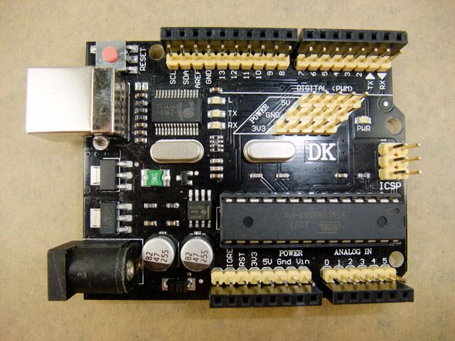
Descriptions
Compatible with Arduino duemilanove 2009 Microcontroller: ATmega328P-PU USB to RS232 Controller: PL2303HX I/O compatible with Arduino UNO R3 Operating Voltage (logic level) : 5V Input Voltage (recommended) : 7.2-11.1V Input Voltage (limits) : 6-20V Package Content
1*DK-duino DKUNO Atmega328p-20PU USB Board 1* USB 2.0 cable
Ethernet Shield With Wiznet W5100 Ethernet Chip
( latest version ) Compatible Duemilanove (168/328) / Mega (1280/2560) / UNO
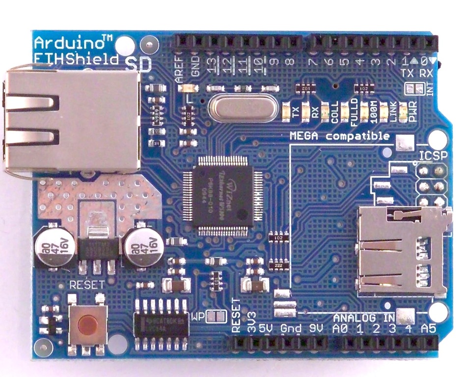
Product Description

     This is the latest version  of the Ethernet Shield. This Arduino Ethernet Shield which is based on the Wiznet W5100 Ethernet Chip gives you an easy way to get your Arduino Online. It is directly supported by Arduino official Ethernet Library. It adds a micro-SD card slot, which can be used to store files for serving over the network. It is compatible with the Arduino Duemilanove (168 or 328), Uno as well as Mega (1280/2560) and can be accessed using the SD library.
The Wiznet W5100 provides a network (IP) stack capable of both TCP and UDP. It supports up to four simultaneous socket connections. Use the Ethernet library to write sketches which connect to the internet using the shield.
6002
circuits
MPPT charge circuit
freechargecontroller.org
Arduino PPT Solar Charger Hardware Description by Tim Nolan 5/9/09
These are my notes on the hardware and schematic for my Arduino Peak Power Tracker Solar Charger project. These notes are based on my schematic ArduinoSolar.pdf on my website www.timnolan.com.
This project is based on the open source hardware platform of the Arduino Duemilanove. I got mine at Sparkfun (www.sparkfun.com) but there are other places you can get them (www.makershed.com). The Arduino webpage that includes links to the Duemilanove schematic is at http://arduino.cc/en/Main/ArduinoBoardDuemilanove.
The Arduino Duemilanove takes care of the microprocessor part of the project. I built the charger part of the project on a ProtoShield Development Kit that I also got at Sparkfun. This is a small prototype board that has connectors to mate directly to the Arduino processor board and bring all the signals up to the prototype space. I was able to fit the complete charger circuit into this prototype space. If you take a look at the photos on my website you can see how the components are placed on the ProtoShield. I've also included the parts list for this project with the Digikey and Sparkfun parts numbers in the file ArduinoSolarPartsList.txt on my website www.timnolan.com.
The charger circuit is basically a DC/DC converter (in a buck configuration) controlled by the software in the microprocessor. The software figures out the voltage of solar panels where the Peak or Maximum Power is produced and controls the DC/DC converter to match the solar panel voltage to the battery voltage. The processor controls the DC/DC converter by generating a PWM signal that switches the MOSFETs at a 50kHz frequency. The transfer ratio of voltage in vs. voltage out is based on the duty cycle of the PWM signal.
Looking at the schematic ArduinoSolar.pdf the connector (J1) for the Solar Panel input is in the upper left corner. There is no protection for polarity reversal so make sure that the solar panels are connected correctly. The solar panel input voltage is connected to the Vin or Raw input to the Arduino board which goes to a voltage regulator to generate 5V to run the processor. The 5v also comes back to the ProtoShield board. The solar panel ground input is connected to the ground of the ProtoShield and Arduino processor board. The solar panel input voltage is divided down by R4 and R5 and sent to the Analog_0 input of the Arduino to be read by the processor.
The solar input current is read by R1 the .005 ohm current sense resistor that generates a very small voltage when the current flows. That voltage is picked up and amplified by IC1 the MAX4173H which is a high side current sense amplifier. The MAX4173H has an amplification of factor of 100. So if 5A is flowing through R1 it generates 5A x .005 ohms = 0.025V x 100 = 2.5V to be read by the processor. The MAX4173H only comes in surface mount SOIC8 package so I used a little conversion board from Sparkfun. I soldered the MAX4173H to the board and then used the 8 pin dip socket to plug it into the ProtoShield board.
C2 is the input filter capacitor that smooths out the input current pulses. Q1 is the blocking MOSFET that keeps the battery power from flowing back into the solar panels at night. Normally this is done by a diode in the power path but a since all diodes have a voltage drop a MOSFET is much more efficient. Notice that Q1 is turned around so the intrinsic MOSFET diode does not conduct. Q1 turns on when Q2 is on from voltage through D2. R3 drains the voltage off the gate of Q1 so it turns off when Q2 turns off.
Q2 is the main switching MOSFET for the buck converter and Q3 is the synchronous switching MOSFET. The MOSFET are driven by IC2 which is an IR2104 MOSFET driver. The IR2104 takes the PWM signal (Digital_9) from the processor input on pin 2 and uses it to drive the switching MOSFETs. The IR2104 can also be shut down with the control signal (low on Digital_8) from the processor on pin 3. Since Q2 is an NFET it needs a gate drive voltage that is 10V higher than the source voltage which is the solar input. So the IR2104 uses a charge pump circuit made of D3 and C4 to boost the gate drive voltage to turn on the high side MOSFET. This charge pump circuit only works when the MOSFETs are switching. The software keeps track of the PWM duty cycle and never allows 100% or always on. It caps the PWM duty cycle at 99.9% to keep the charge pump working.
D1 is an ultra fast diode that will start conducting current before Q3 turns on. It is supposed to make the converter more efficient but it may not be necessary. L1 is the main inductor that smooths the switching current and along with C3 it smooths the output voltage. Since the DC/DC converter is switching at 50kHz the 33uH value of the inductor should be sufficient. C7 and R10 are the snubber network used to cut down on the ringing of the inductor voltage.
To measure the battery voltage R6 and R7 make up the voltage divider which feeds the signal to Analog_2 to be read by the processor. J3 is the battery connector, there is no reverse polarity protection so make sure the battery is connected correctly. I did not have space to fit a fuse so make sure you put a fuse in your battery wiring harness. Batteries hold a lot of energy and you can start a fire if something goes wrong and you do not have a fuse. Also you might want to put a diode in battery wiring harness during development. If you look at the schematic you can see that if Q3 ever stays on for any length of time that it is a dead short across the battery. This would not happen in normal operation but if you have a software bug or you stop the system to load new software it might end up with Q3 on. A diode would stop this from happening but you would lose efficency in the diode voltage drop. Once you have the software worked out this diode is no longer necessary. I've burned up my fair share of MOSFETs before I figured this out.
I've included the two LEDs and switch that are on the ProtoShield board in my schematic. I use the one LED JC2 as a heartbeat indicator in my system.
12vdc-5vdc step down converter
using a $.37 MC34063ECN Switching Converters, Regulators & Controllers 3.0 to 40V DC-DC Cnv from mouser datasheet
The simplest way to reduce the voltage of a DC supply is to use a linear regulator (such as a 7805), but linear regulators waste energy as they operate by dissipating excess power as heat. Buck converters, on the other hand, can be remarkably efficient (95% or higher for integrated circuits), making them useful for tasks such as converting the main voltage in a computer (12 V in a desktop, 12-24 V in a laptop) down to the 0.8-1.8 volts needed by the processor. http://en.wikipedia.org/wiki/Buck_converter
switching converters explained
arduino
resistor color codes
refs
- http://www.qsl.net/ve3lny/index.html
- arduino-info - Nrf24L01-2.4GHz-HowTo
- Arduino Differential Conntroller | Arduino Solar Hot Water | Differduino | Nateful
- My Page - GarageLab (arduino, electronics, robotics, hacking)
- Ethernet Arduino Library, using WizNET Ethernet modules with Teensy
- PC/CP300 Electronics Laboratory II
- 8-Channel 12V Relay Module for Arduino PIC ARM AVR DSP - Free Shipping - DealExtreme
- Shield stacking headers for Arduino ID: 85 - $1.50 : Adafruit Industries, Unique & fun DIY electronics and kits
- Circuit Boards within Project Accessories - MCM Electronics Category
- Relays and Practical Circuits
- Embedded PIC based SBC board with Ethernet, RS232, I2C, 12 Analog Inputs, 32 Digital I/Os, free TCP
- tuxgraphics.org: An AVR microcontroller based Ethernet device
- FreePCB: freeware PCB layout software
- Parts & Kits for Arduino Online, Buy Microcontroller Boards, Electronic Components for Arduino - EtherMega (100% Arduino Mega 2560 compatible with onboard Ethernet) - Freetronics
- TCP/IP Stack, FAT16 System on a Microcontroller - CodeProject
- Start Using HTML5 WebSockets Today | Nettuts+
- www.clare.com/home/pdfs.nsf/www/CPC1998.pdf/$file/CPC1998.pdf
- How To Solder - Soldering Tutorial
- Solid State Relays
- Transistor Circuits
- Datasheet4U.net - World Electronic Components Datasheet Search Site!
- [http://nl.bu.edu/research/software/downloads/ Downloads �� Software �� Research �� Neuromorphics Lab]
- Graphical Resistance Calculator
- How to Build a Robot Tutorial - Society of Robots
- Reverse-Engineering an LCD Display
- SMPS Basics - The Buck Converter
- GuideCircuit : Free Electronics Circuit on website ; Digital thermostat
- GuideCircuit : Free Electronics Circuit on website ; Schematics of Digital thermostat
- ===newmodel===
basics
- LED flat section toward ground
- breadboard power bars 1/2 of long side
op amps
on using wall warts in circuit design
http://www.dxing.info/equipment/wall_warts_bryant.dx
sample circuits
http://www.discovercircuits.com/S/solidstate.htm
http://members.vol.at/home.floery/electronix/picnic/documentation.html
http://www.edaboard.com/thread5683.html
http://microcontrollerkits.blogspot.com/2011/11/arduino-microcontroller-control-tcpip.html
http://tuxgraphics.org/electronics/200606/article06061.shtml
http://8bitmicro.blogspot.com/2012_02_01_archive.html
http://www.freetronics.com/products/etherten